Fuel Tank
Balance
Sigh, so close yet so far away. Finally had a break in the weather and was able to put the airplane on the scales. The results confirmed my fears, the center of gravity is too far back.
Center of Gravity
For an airplane to have proper pitch control it must balance at a specific location. Too far aft and you can’t pitch the nose down, too far forward and the nose won’t pitch up. On this airplane the safe range is 21%-30% of wing chord with the ideal location at 28%. With a cord of 54″ the CG must between 11.35″ and 16.2″ behind the leading edge of the wing.
Measuring the CG
Measuring the CG is quite simple. The airplane is first placed on a level surface. A scale is placed under one wheel and wood blocks, the same height as the scale, are placed under the other wheels. This way the airplane will remain level as we move the scale between each wheel to measure the weight.

Next you must pick a datum, this is just an arbitrary reference point on the airplane. Then measure the distance between the datum and the center of each wheel, this is referred to as the arm.
With the airplane ready to fly, sans fuel, with pilot, me, in the cockpit we weighed each wheel. Each measurement was taken for times too ensure we got consistent results and then averaged.
| Location | Weight (lbs) | X Arm (in) | = Moment (in lbs) |
|---|---|---|---|
| Nose Wheel | 34.7 | X 11.8 in | = 409.46 |
| Right Wheel | 239.9 | X 53.69 in | = 12,880.231 |
| Left Wheel | 240.85 | X 53.69 in | = 12,931.236 |
| Total | 515.45 | 29,220.927 |
The CG is calculated as total moment divided by total weight
22,220.927 ÷ 515.45 = 50.87″ from datum
The leading edge is 32.75″ from datum placing the CG at 50.87″ – 32.75″ = 18.12″ behind the leading edge of the wing.
That’s nearly 2″ behind the limit, what’s worse is adding fuel will only push the CG even farther back.
How did we get here?
I’ve made a few changes to the airplane from its original design.
- Added the BRS for safety
- Added disk brakes, for safety
- Added a strobe on the tail, for safety
- Paint scheme, because it must look good
- Slightly heavier harness, for safety and comfort
- Added wing tanks instead of the fuselage tank, mostly because I hated getting my toes stuck on the fuselage tank when working the rudder pedals.
So did all of those changes cause the problem?
Nope, it’s easy to calculate, measure the arms of those items, subtract their weight and moments from the data above and she is still tail heavy.
The rest can be explained by knowing the history of this design. Originally it was designed for the now discontinued Rotax 277, which happens to weigh 20lbs more than the Hirth F33 I have.
Math says removing my changes and adding 20lbs to the engine resolves the problem. So she would have been tail heavy even if I had not made the changes. But I did manage to make it worse.
What to do about it?
Seems like I have two options, get a bigger heavier engine or add weight to the nose to make it balance. I posted on LonesomeBuzzards.com to get some opinions from the community. The community basically had two suggestions, add weight and give it a try or better get a bigger engine because you need the extra HP with that much weight.
Still not sure what to do I made the hour trip to visit my friend David Gohn. After looking over the numbers he suggested I should add the weight to make it balance leaving more money to build the next airplane. His assurance that the F33 was perfectly capable of flying this airplane safely was helpful.
Andy Humphrey from heavenboundaviation.com also felt the F33 would be fine. But suggested that if I’m adding weight, try to find a way to attach it directly to the engine since it might help dampen some of the vibration that the F33 is notorious for.
So I got a piece of 3/8″ thick mild steel to make a new motor mount from.
After cutting it with a reciprocating saw and drilling holes it weighs 8.264lbs, almost 1/3 of the weight needed to get the airplane balanced.

After a trip to the disc sander to cleanup edges and baking on some powder coating the new mount looks great and weights 8.208lbs.

Removed the lithium battery and replaced it with a sealed lead battery that weighs 26lbs
With those two minor changes she balances!
The CG range is 21-30% of wing chord with 28% being the ideal CG. After adding the weight she balances at 28.2% and 28.8% with empty and full fuel tanks.
Conclusion
Had I known that she would be tail heavy I could have made some small changes such as extending the nose a bit and building my own custom fuselage tank instead of using wing tanks.
I’m satisfied with the results, the gross weight is more than I wanted but within the design limitations of this airframe.
Just a few more items to wrap up and I she will be ready for the airworthiness inspection.
Curtis Drain Valve Hose
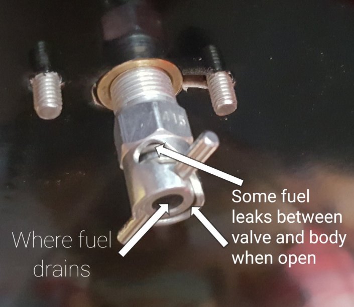
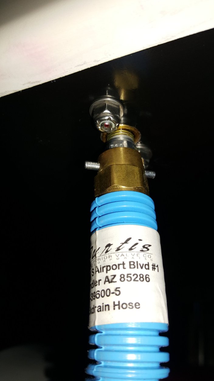
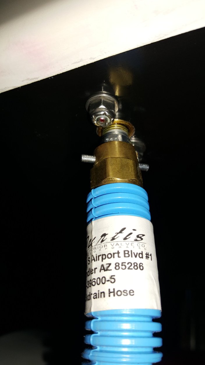
To drain the fuel from the airplane I installed some Curtis quick drain valves CCA-4850 and purchased the Curtis drain hose assembly CCB-39600-5. They claim that “Waste liquid flows through 5 feet of high grade vinyl tubing, preventing messy spills and making a cleaner, safer environment.” A better description would have been “95% of the fluid flows through the hose, the rest makes a messy spill”
At first I thought maybe the particular valve I got was the problem but looking on their site I see that my valve is listed with the hose I have. Upon further inspection of the valve I see the problem. There is no seal between the valve and the valve body when the valve is opened. So some of the fuel leaks between the valve and it’s body while the majority of it runs through the valve into the hose.
I removed the brass piece from the drain hose assembly and decided to make a simple modification. The brass is shaped like a little cup and can catch the fuel that leaks between valve and valve body. So all I needed to do was drill a small hole to allow the captured fuel to drain into the hose instead of overflowing and making a mess. I used a 0.09″ drill bit inside the nipple at a slight angle.
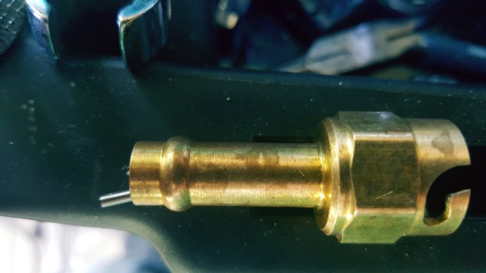
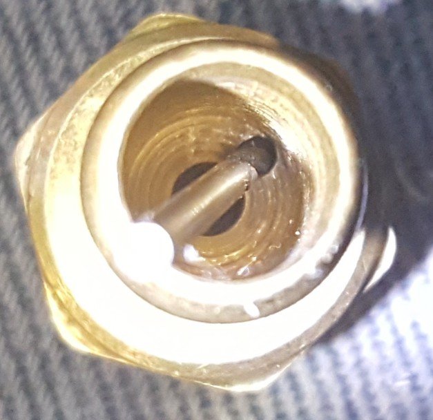
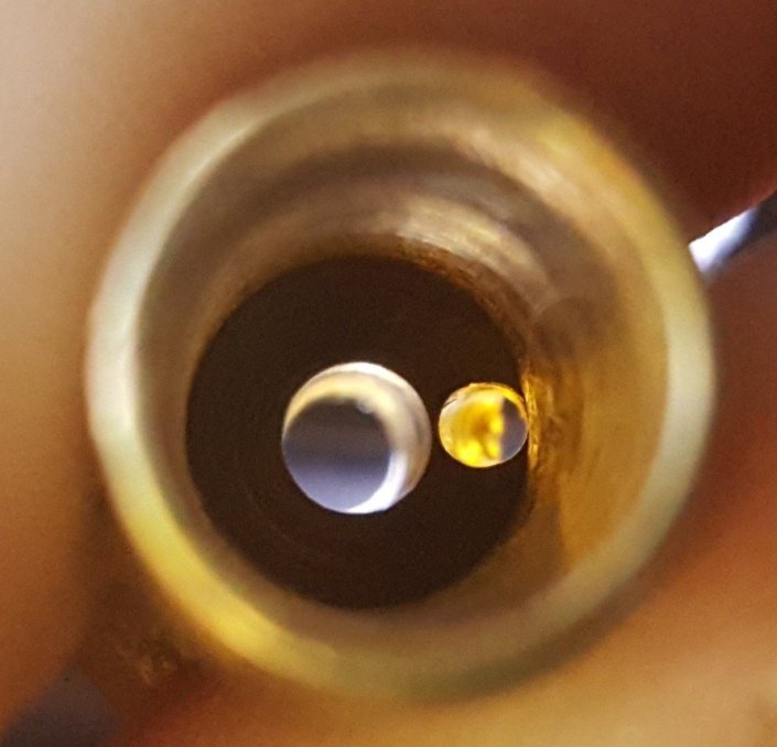
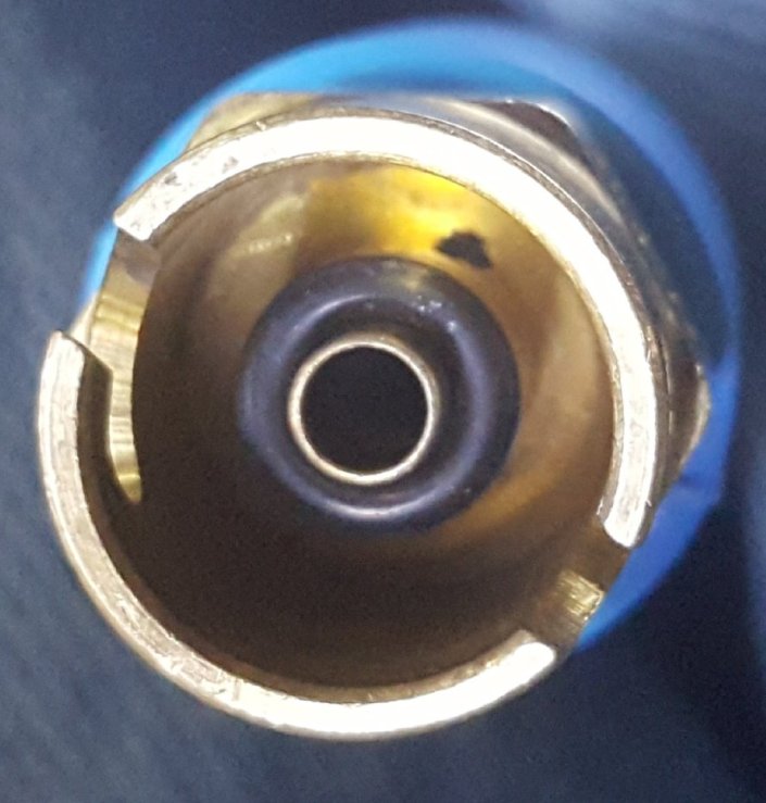
After trying out my modified drain hose I discovered that it does work much better but not perfect so I added a second drain hole on the opposite side. At this point I’m satisfied. Some fuel vapors will come out around the connection and sometimes a little will condense on the valve tabs. But fuel was not pouring down the outside of the hose and making a puddle on the floor like it did before the modification.
If it’s not obvious, it has one drawback, if the drain hose is obstructed in any way the fluid will follow out the holes, overflow the cup and make a big mess. Maybe a valve and a nipple to drain the fuel would have been a better choice.
Wing Tanks Installed
To cushion the bottom of the tank I got some 1/8″ thick neoprene. The best deal I found was sold as “tool box drawer liner.” I cut it so it is wider than the bottom so it wrapped up the sides a little then notched out the inboard rear edge to match the plywood.
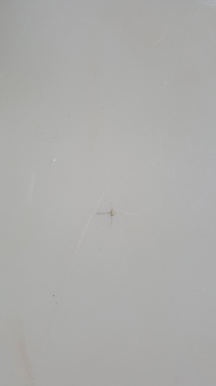
The tank needed two holes, one for the drain and one for the fuel level sensor. I first drilled a small pilot hole then used a 1/2″ forsner bit. Never use a regular twist drill bit for this step, you will end up with a triangular shaped hole instead of perfectly round and the bushing won’t seal.
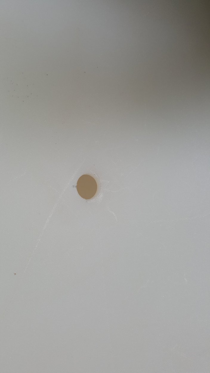
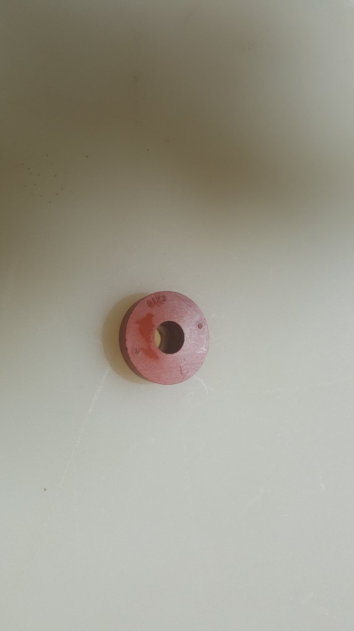
Then installed the rubber bushing.
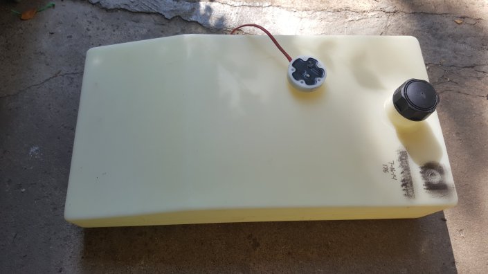
At this point I realized this particular tank is too deformed to install the fuel level sensor because the top and bottom are curved inward so there is not enough clearance for the sensor.
Knowing these tanks do expand the first time they are filled with gasoline I had to stop the installation and fill this tank with gas and hope that resolves the problem. After a few days the tank was still deformed, so I sealed the tank and put a few psi of air pressure in it. The following day I removed the air pressure and let it sit with gasoline in it. After a few more days the tank is back to its normal shape and has held that shape for over a week.
Now I can install the fuel level sensor. I made sure that the sensor was about 1/4″ above the bottom of the tank and pressed it into the bushing.
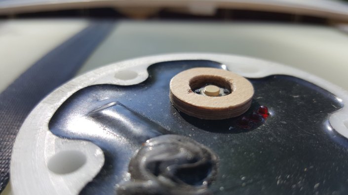
I was concerned that the polycarbonate cover might bump the calibration switch on the sender so I cut a ring of plywood to protect the switch. I used some silicone to hold the ring in place.
The drain hole in the bottom of the tank was drilled and fittings installed.
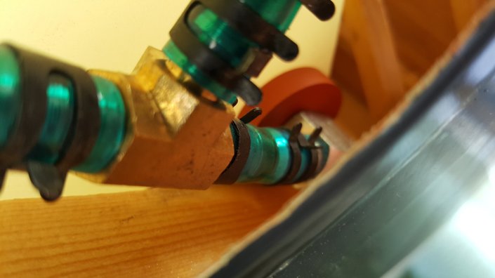
Now the tank was installed into the wing. To hold it in place I purchased some tie down straps. They were way too long so I cut them shorter and heat welded the end so it does not fray. I routed then under the plywood and diagonal supports then over the top of the tanks.
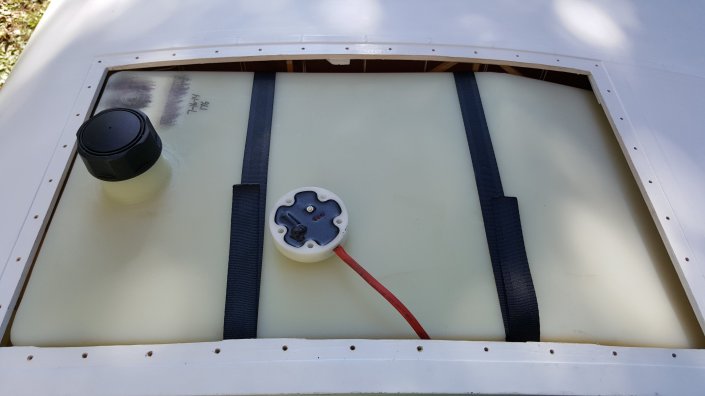
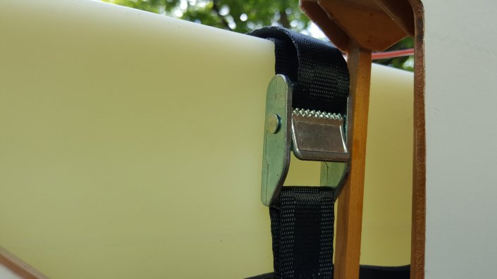
The fuel line was routed from the elbow to a tee. Then to the drain and quick disconnect. This was not an easy task to accomplish without kinking the lines. It would have been easier if the quick disconnect was moved an inch or two forward but that would have made the quick disconnect higher which is undesired and more likely to get bumped by my elbows when sitting in the cockpit. Maybe cutting one barb off of the tee would help too.
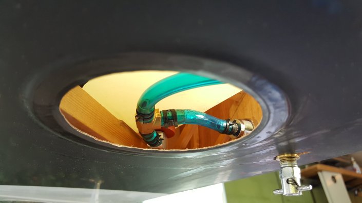
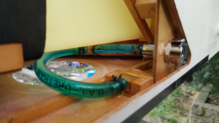
After installing the cover panel I’m amazed at how well it looks.
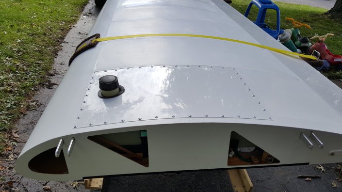
Not much remains on the wings now. Grease aileron bearings, safety wire aileron bracket bolts, install wing tips and I need to get the rest of the wing polished so it shines like the tank cover and ailerons.
Fuel Sender Wires
Time to route the fuel level sensor wires. The first thing I did was mount the wings and locate a location to drill a hole for the wires. After drilling the hole I added a grommet.
After locating the hole I determined how much wire needs to protrude from the fuselage so they can be easily disconnected after removing the wing.
The sensor outputs need routed to the fuel selector switch so I decided to make some splices near the sender switch to accommodate this. I routed the left fuel sensor wire down the left fuselage side, across the floor and up the right side and through the grommet. On the right side near the fuel selector switch I spliced in the fuel selector and right side sender wires.
The red and black (power and ground) are spliced to the right side sender so both senders get power. The white wires from each sender are spliced to the wire going to the selector switch, right to red and left to black. The white wire from the dash and to the selector were spliced.
Terminal ends were added, the resulting harness looks pretty good.
Behind the dash the black is connected to ground, red to power and white to the green EIS Aux input.
Fuel System – Firewall Forward
Two fuel lines pass through the firewall. One is from the electric fuel pump, the other is gravity feed. In the picture below the right line comes from the electric fuel pump. The inline check valve ensures fuel can only flow towards the engine.
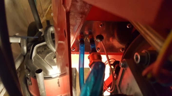
After the check valve is a tee, shown below. Left side connects to the electric fuel pump check valve, right to mechanical pump check valve and the top goes to the carburetor. Behind the tee is the inlet for the mechanical pump. It’s fuel line is connected to the left line in the picture above. Rest assured, the top hose now has a clamp, it was not installed when I took this picture.
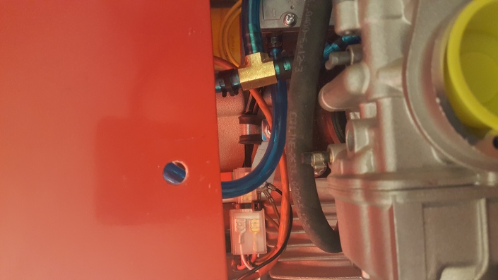
Below you can see the mechanical fuel pump on the right. The outlet connects to a check valve that’s connected to the tee. I wrapped some silicone tape around the check valve so won’t chafe nearby components.
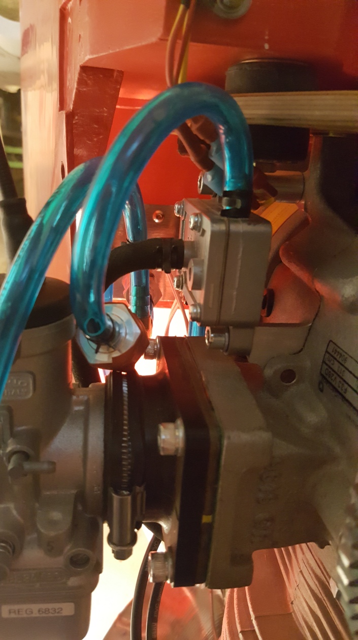
The outlet of the tee connects to the fuel inlet banjo on the Dellorto PHBE34BD3 carburetor.
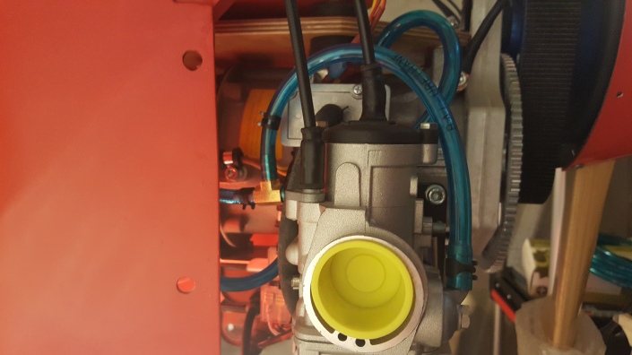
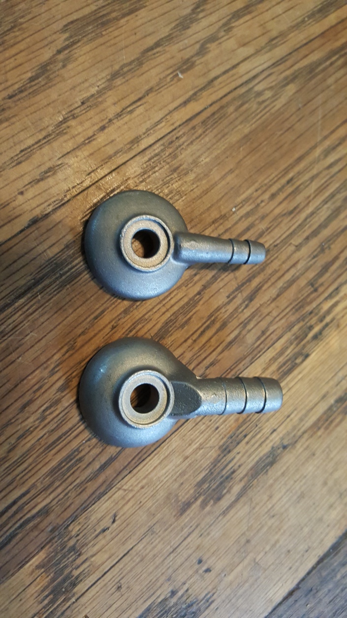
This is one complaint I have about the Hirth F-33, it came with the fuel pump and carburetor. The outlet on the fuel pump is made for 1/4″ (6.3mm) ID hose but the inlet on the carburetor is only 6mm. To resolve this I ordered a new fuel inlet banjo, Dellorto part number 6273 that has a larger diameter barb.
Now all I need to do is fasten the fuel tanks in the wings and install the air filter and she is ready to run!
Fuel System
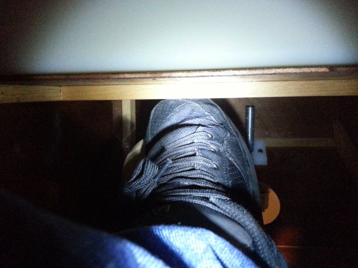
I’ve spent many hours researching and thinking about the best way to design the fuel system. Originally I planned to use the five gallon fuselage tank that came with my kit. But after deciding to register my airplane instead of going Part 103 I decided to add wing tanks. It would have been nice to use the fusealge tank as a header tank but the fact it interferes with my toes when working the rudder pedals I decided it would be best to remove it. Maybe I can build a custom header tank that does not hit my toes but for now I decided to move forward without it.
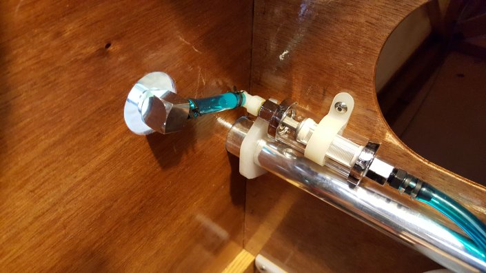
Starting at the wing we have the valved quick disconnect. I used a 90° male end to keep the hose along the fuselage side.
Directly after that are the fuel filters. This location is easy to access for service and inspection.
I still wanted some sort of header tank to ensure the fuel pumps won’t suck air when I’m banking and the tank is not full. The simplest solution to this was to add an inexpensive one quart tank for each wing tank.
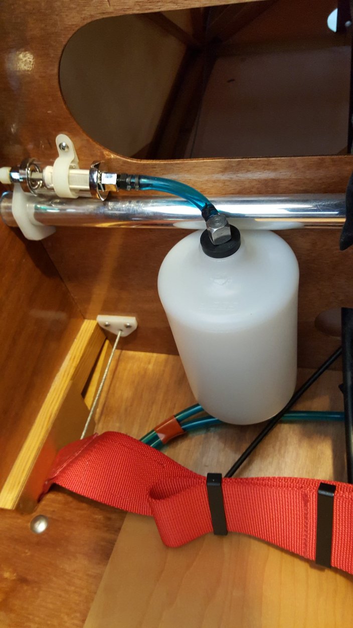
These were originally designed for radiator overflow and came with a small vent hole that I sealed with some heat.
The bottom of the tanks are routed to the right and left input of the selector valve. This valve is from a jet ski, easy to find so it can be replaced periodically before it fails. It only provides left, right and off positions. For midwing airplanes, like mine having a both position could result in the pump sucking air from an empty tank instead of fuel from the full tank.
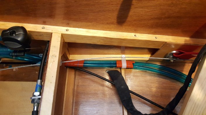
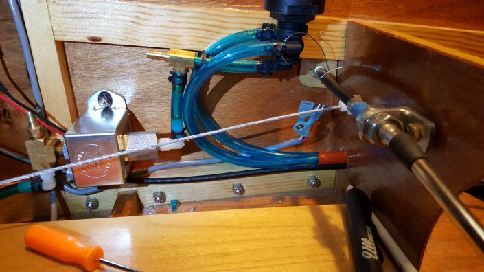
After the valve is a tee, each outlet is connected to a different fuel pump. An electric pump and a mechanical pulse pump on the engine. I mounted the electric pump in the fusealge right after the valve.
Some day I’ll need to drain all the fuel so I can replace fuel lines, valves and to service the fuel filters. The outlet of the electric pump connects to a tee, one outlet towards the firewall, the other to the Curtis drain valve I installed on the bottom of the fuselage.
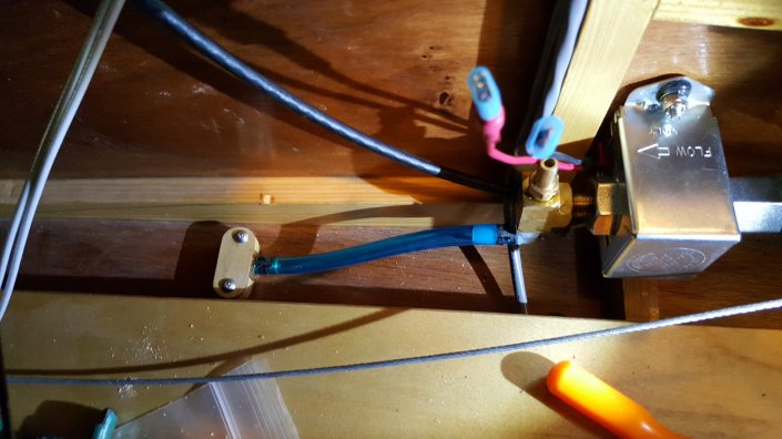
Mounting the valve was simple after making a retaining bracket out of some plywood and a piece of RS-7. The bottom plywood is made from 1/8″, this is needed to lift the brass piece off the floor to leave room for the hose clamp.
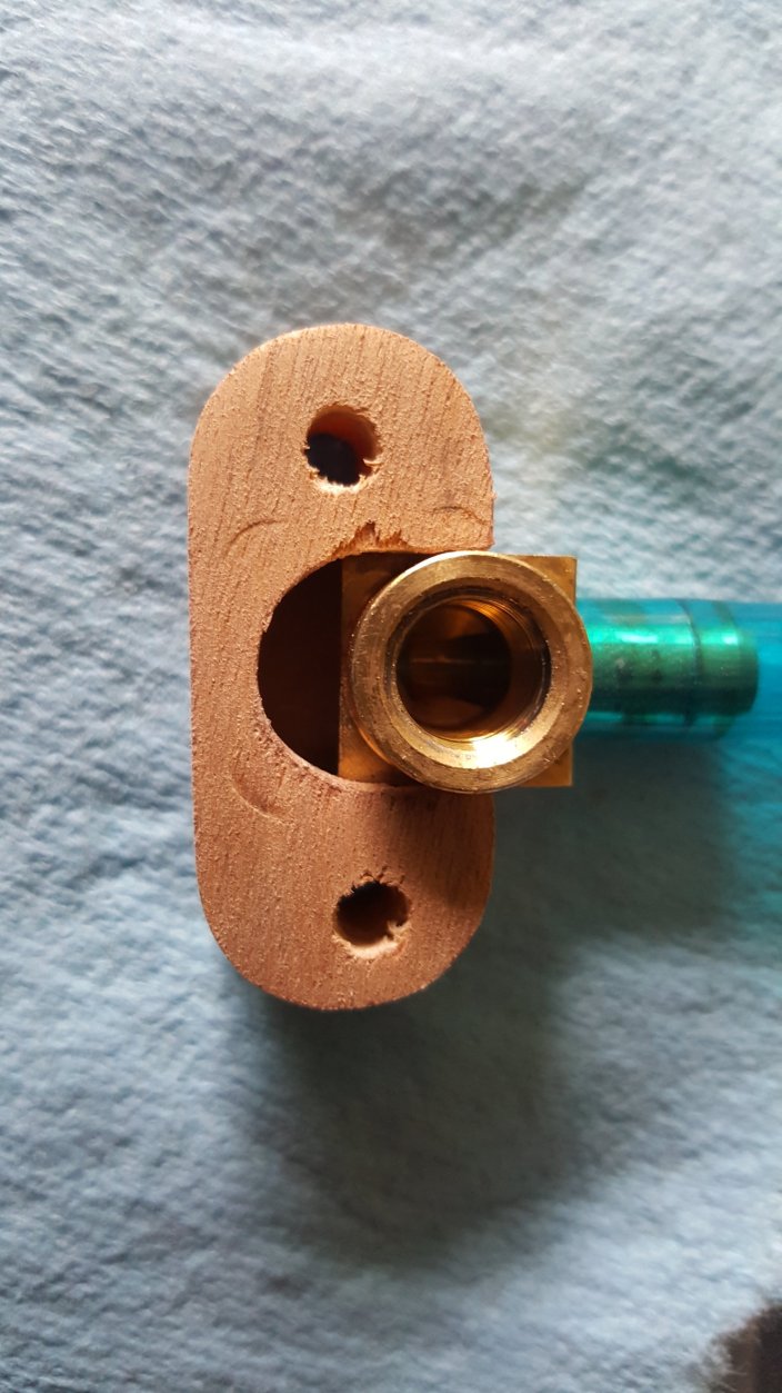
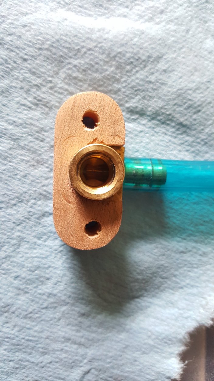
The RS-7 was cut so it fits around the brass piece and then some 1/16″ ply was added as a top.
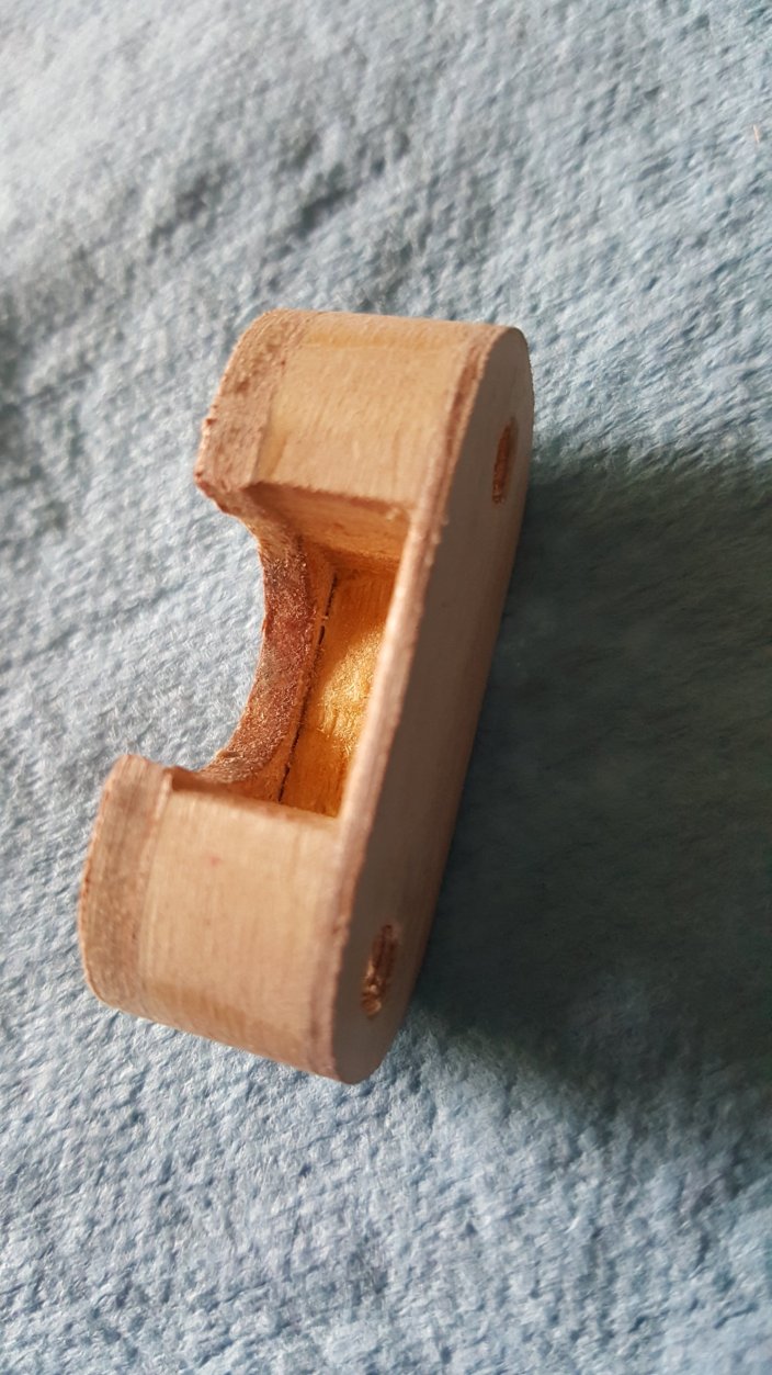
The round part on the brass is 0.550″, I used a 1/2″ forsner bit and a file to make the hole. I placed the brass piece in the hole and slid the retainer over the brass to through drill the two mounting holes.
Next I used a small file and made a notch from the body hole to one of the mounting holes.
This will allow the Curtis valve to fit through the hole.
The retainer is slid over the valve and mounted in place.
Some of these pictures were taken before I tightened down the drain valve into the brass. Before I did that I coated the threads with Permatex Aviation Form-A-Gasket to help ensure I have no leaks.
Added some washers and lock nuts and the drain is ready for use.
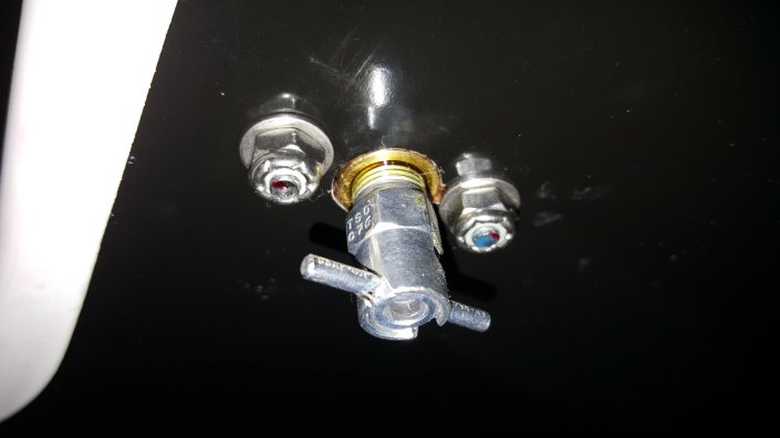
The nice feature of these valves is that they have a mating drain hose that locks onto and seals against the valve so you can drain without spilling or dripping fuel.
To speed up draining just turn the Facet pump on, using the selector valve you can select what tank to drain.
I used some copper pipes to make the penetration at the firewall. The reason I did this is for safety. If there is ever a fire in the engine compartment the blue fuel line will melt from the heat and I’d have fuel leaking by my toes near a fire. The long copper lines will take some time to transmit heat from an engine fire all the way back to the blue lines.
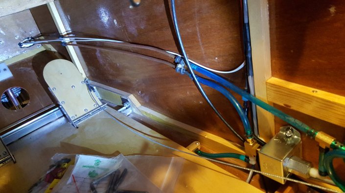
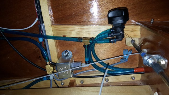
I’ll cover firewall forward in a future post.
Fuel Gauge
Started working on the electrical wiring and discovered that the EIS 2000 I have only supports a single fuel level input. They sell the EIS 2000 as a two or four stroke model when in reality it does not matter if you have a two or four stroke the difference between the two models is features not engine type. When I build the next airplane I think I will build my own EIS or use the flybox.
So the Grand Rapids folks suggested using a switch so I can select what tank level I want to monitor. After thinking about this for some time I decided this is the best option but that it needs to be implemented carefully. Imagine monitoring the full tank but running the engine from the empty tank. That could result in a bad day.
In designing this I decided the goals should be as follows:
- The position of the tank selector valve dictates what fuel tank is monitored by the EIS
- If the fuel selector valve is in the off position then the EIS should see an empty tank triggering the warning
The typical inexpensive fuel selector valve is not suitable for triggering some electrical switches. I ended up purchasing a WSM 006-600 jet ski fuel valve on Amazon.com and a couple of 2750017 micro switches from the local RadioShack.
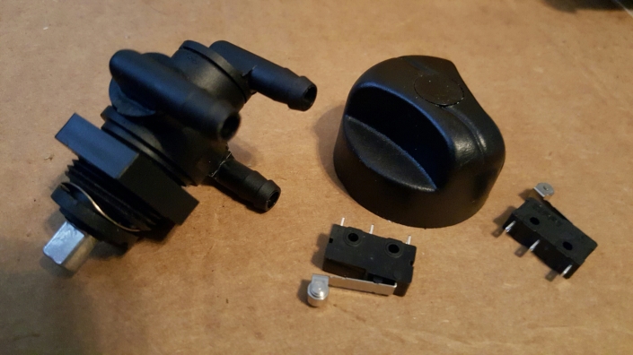
Using a file I put a flat spot on the knob that was parallel to the flat side of the D hole in the knob. The location of the flat spot is important so if you have a different valve you might need to change the location.
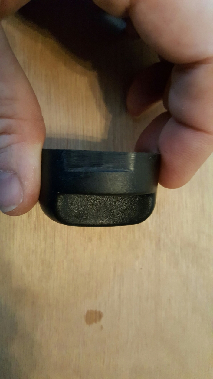
When the knob is installed on the valve the flat spot should line up with a micro switch roller only when the valve is turned to the left or right tank. This will require the switches to be mounted 180° from one another. I used OnShape.com to make a drawing that I printed out in reverse on toner transfer paper. This will provide accurate centers for the holes and the labels for the valve.
Putting the switches to their marked locations on the toner transfer paper you can get an idea of how this will work.
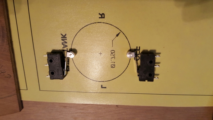
I varnished a piece of plywood, sanded it smooth and applied the toner transfer. Then the parts were cut out and drilled. A smaller valve support plate needs to be 5/8″ away from the panel so the notch in the knob is just below the plywood.
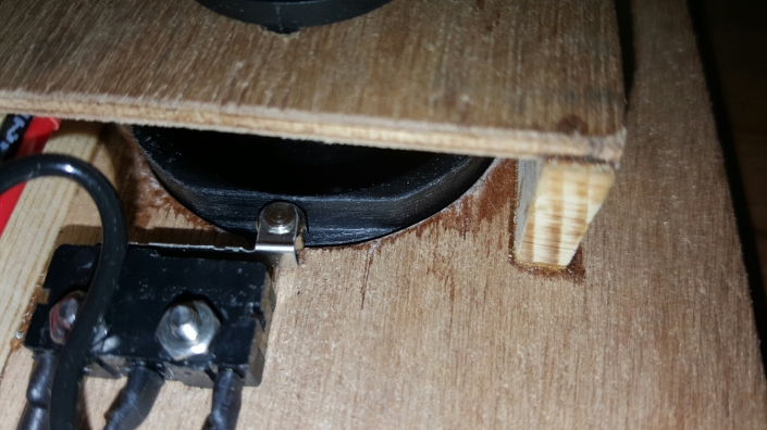
On the outside, for asthetics I used 1/4″ X 3/4″ pine. A 1/8″ notch was cut into the outside piece and the valve support set into the notch. The inboard side used a small piece of 1/4″ X 5/8″ pine. Alignment is important so I glued this together with the valve and knob installed to keep everything indexed.
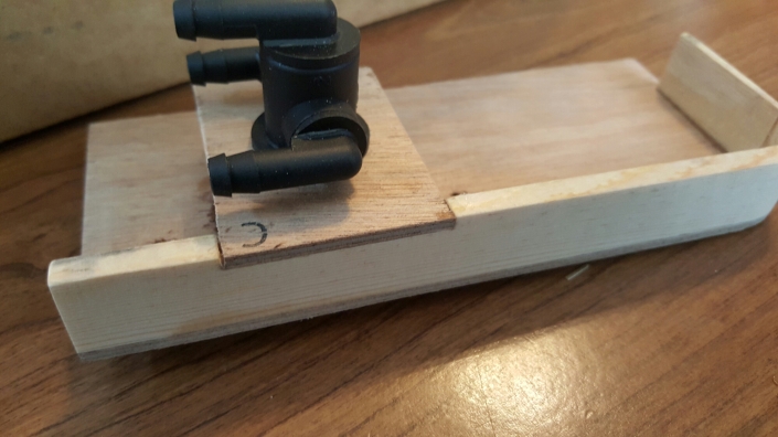
Once the epoxy cured the switches were mounted using #3 screws and the valve installed.
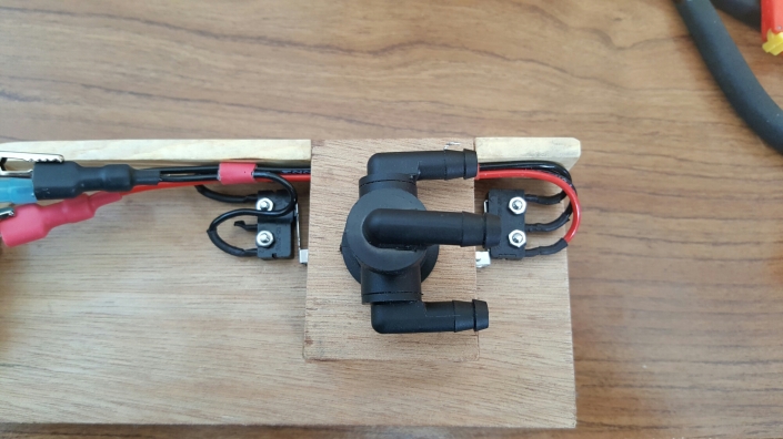
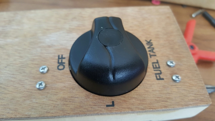
The electrical wiring did take a little bit of planning. I wanted to make sure that should there ever be a malfunction that only a single fuel level sensor would be connected to the EIS. Here is the wiring diagram that does this:
http://schematics.com/embed/fuel-sender-selector-46440/full
Before takeoff simply turning the valve to all three positions will confirm if the system is functioning properly.
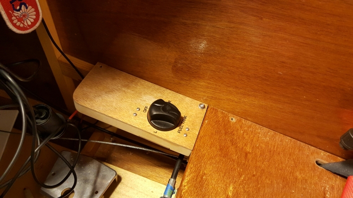
I think this turned out well, looks pretty good mounted on the fuselage side.
Wing Tank Part Four
The lexan is trimmed to fit into the opening, since it is 1/16″ just like the plywood trim around the opening the top surface is flush giving it a great look.

Holes are drilled every 2″ around the perimeter of the lexan then screwed into place.
To prevent the holes in the wood from stripping over time some thin CA is soaked into the holes and allowed to dry before reinstalling the lexan cover.
The lexan is marked and drilled to create an opening for the filler neck. To locate the filler neck position I installed the tank and used a square to locate the center front of the neck. Note that this picture was taken after making the hole and is intended to help show how this step was performed but this step was performed without the lexan in place.

Then the lexan was installed and the center of the filler neck was marked then drilled using a 2 1/2″ hole saw.

The final result looks great.

Because I will need to remove the wings I wanted quick disconnects for the fuel line and some way to drain the fuel.
For the drain I got a 90° 1/8″ NPT to 1/2″ barb brass and a quarter turn drain valve.

Some blocks were glued in place to hold the drain and a piece of plywood is screwed on top to keep it from moving.


A piece of 1/8″ plywood was glued to the root rib to hold the panel mount quick disconnect.

With the disconnect removed the wing was mounted if the fuselage so the hole could be marked and drilled into the fuselage. Once drilled the quick disconnect was reinstalled to test the fit.

The hole is just large enough so I can get my finger into the release tab. The 90° make disconnect will make routing the fuel line’s much easier.

Wing Tank Part Three
The RS-5891 plywood bottom is cut to shape and glued to the RS-9 supports and drag brace. Unlike the plans I decided to extend the rear of the floor to the rear spar by gluing an extension to the plywood.

Two RS-4 are glued to the ply in front of and behind the tank to keep it from sliding forward and aft.
A RS-3 is glued between rib #2 and #3 to reinforce rib #2.

Wing Tank Part Two
With the drag brace supports in place it’s time to frame in the opening at the top of the wing. I cut a piece of RS-17 to length and notched the side of it where the gussets are located on rib #2 then glued to the side of the rib.


Next I located the rear of the opening and cut the plywood connecting the root and #1 rib. Then removed the front portion of the plywood.

Another RS-17 was cut to fit between the root and #1 rib. At the rear of the opening the RS-17 is notched to make room for a horizontal RS-17.
After checking the fit it was glued into place.

Once the glue was dry rib #1 was cut at the rear of the opening where the notch was made in the RS-17.
Another RS-17 is cut and glued into the notch forming the rear of the opening.

A 1/16″ ply gusset is added to the bottom at ribs #1 and #2 to strengthen the rear opening.

A 1/16″ piece of ply is added to the rear of the opening and over the root rib.

Lastly a piece of RS-3 is glued to the front spar to provide a surface for attaching the lexan cover.

Now it’s time to install the tank floor.


