BRS
BRS Rocket Installation
I need to do a final weight and balance check with the airplane in its final configuration so it’s time to get the parachute rocket installed. The installation is pretty simple.
Just a few parts are needed.
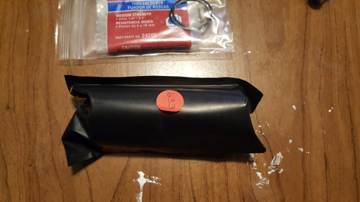
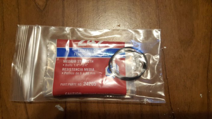
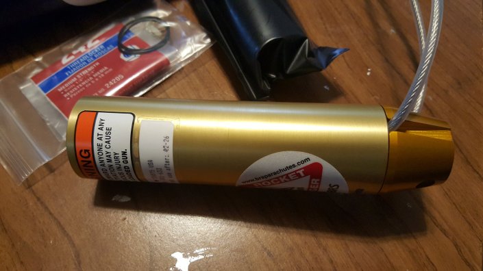
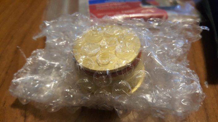
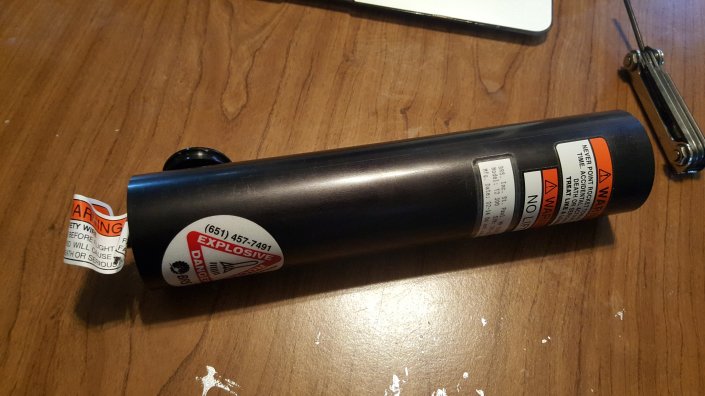
Opened up package of solid rocket fuel.

I placed it upright on the table and set an o-ring inside the cardboard tube then slid the rocket over the fuel.


Carefully turned the rocket over and installed the other o-ring inside the tube.

The cap was removed from the packaging and loc-tite added to the threads.

The cap was tightened down using an adjustable wrench.

Not it’s time to remove the ignition from the launch tube, just needed to remove the two screws on the mounting ring.


One side of the ignition had a three hole between the o-rings, this needs lined up with the hole in the nozzle.

Then the rest are pushed together and the nylon screw is threaded in to hold them together.


The cables need curved the opposite direction, doing this next to the nozzle helps the assembly for into the tube better.

The whole assembly is slid into the tube and aligned with the holes in the body. Loc-tite is used on the screws to ensure they do not come loose.


The cables are feed through the eye and the plastic cap installed into the end of the tube.

That completes the rocket assembly. I attached the rocket to it’s mount and adjusted it so the exit point is between two stringers.

The rocket cables were attached to the clasp under the front flap of the parachute. I could not get a picture of this in the tight space.
At the rear of the ticket the activation cable was bolted to the ignitor and then the rear come watch screwed into the launch tube.

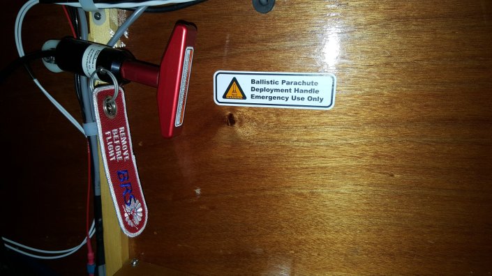
The last item was installing the warning labels.
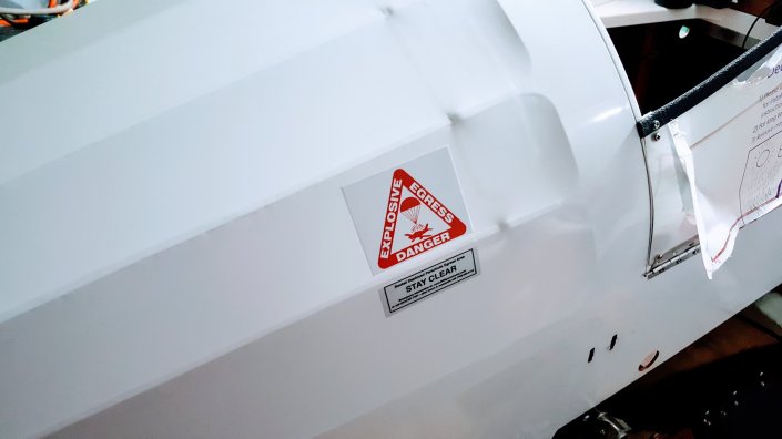
Remove Before Flight!
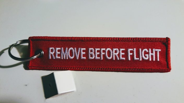
Various parts of the airplane need to be locked for safety or plugged to keep bugs/debris out when the airplane is parked and not in use. These locks and plugs are usually attached to a flag stating “Remove Before Flight.” I purchased some inexpensive, well made, keychains for my flags.
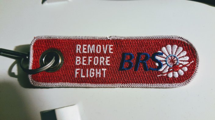
The BRS ( aka ballistic parachute ) came with it’s own flag. This is for safety because you do not want to accidently activate it. It does not have ballistic in it’s name for show, that rocket needs treated like a loaded gun.
The static ports are used to measure atmospheric air pressure and are integral to the air speed indicator (AIS) and altimeter. I bent a small piece of music wire that attaches to the keychain and doors snuggly into the static port.
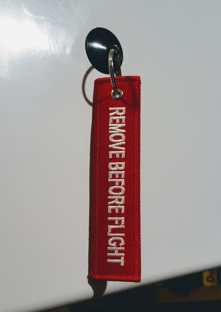
Maybe not necessary but seemed like a good idea I got a small rubber stopper and eye bolt to make a plug for the exhaust.
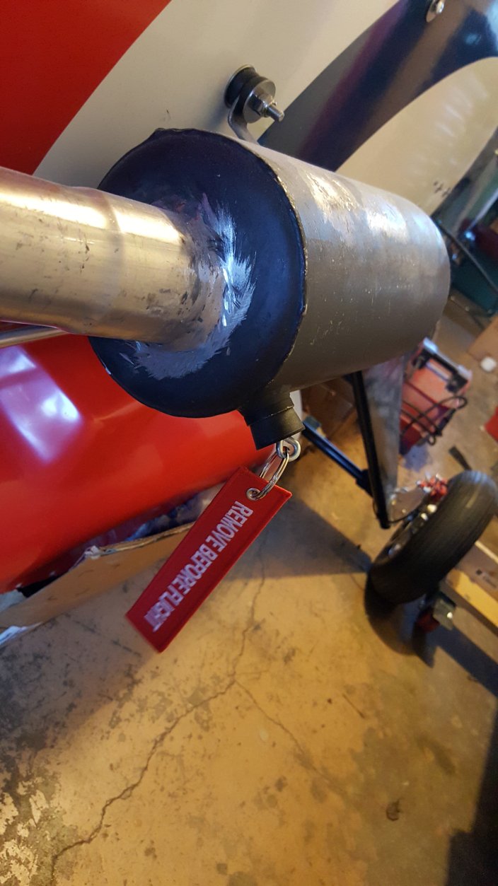
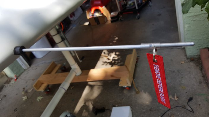
The pitot tube, for the AIS, was a little more difficult to block because the tube can be removed. We not to plug the hole the tube goes in or the end of the tube when it’s installed.
Drilled a hole in the side of a 1/4″ aluminum rod to attach the form.
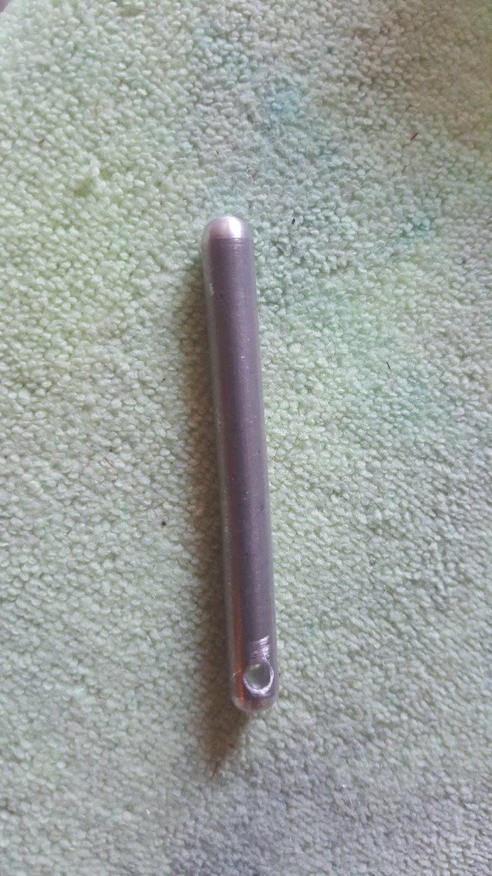
The rod can easily plug the pitot holder.
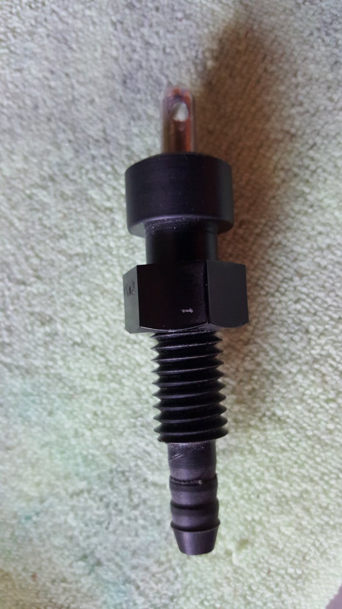
Added a piece of 1/4″ ID tubing, this will be used to plug the tube when it is installed on the airplane.
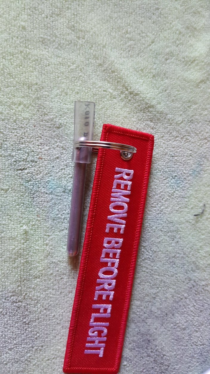
With the pitot tube removed the hole is easily plugged and looks nice.
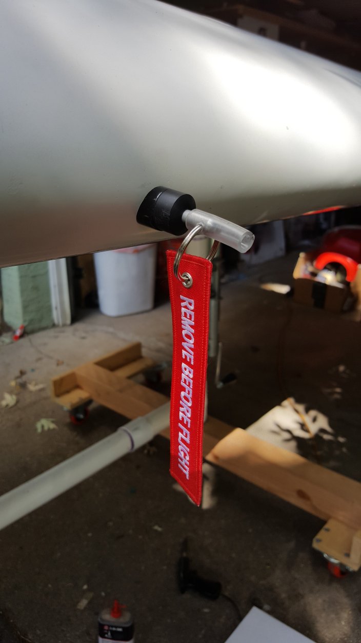
When the pitot tube is installed the same flag can plug the hole. The only downside is that it does add a couple inches to the length.
Brakes and BRS Bridles
Awhile back I ordered some black plastic clips from AliExpress.com to hold the bridles for the parachute in place. This weekend I decided to put them to use. When I got started I also decided to tackle the brake cables since it looked like I could route those with the bridle clips too.

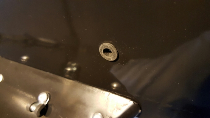
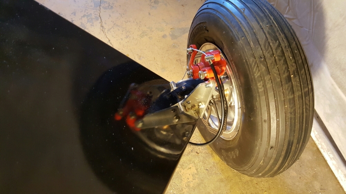
The brake cables exit the fuselage near the front of the landing gear on each side, I added a small grommet to this hole to reduce chafing.
To keep the cables from flapping in the breeze I added a couple of rubber lined cable clamps to the landing gear bolts. The cable routed through the clamps then down the landing gear leg along the bridle that is secured with the plastic clips.
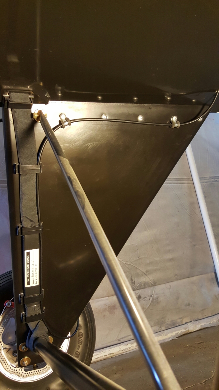
The grade cable the runs around the from of the gear into the caliper.
I also used the bridles clips inside the fusealge so they don’t get tangled up with other things. These clips are a little too tall so they don’t clamp the bridle. I put a small piece of foam on the top on in the picture below. Next time I’m at the hardware store I plan to get some self adhesive black foam weather striping to use in the few places where this matters.
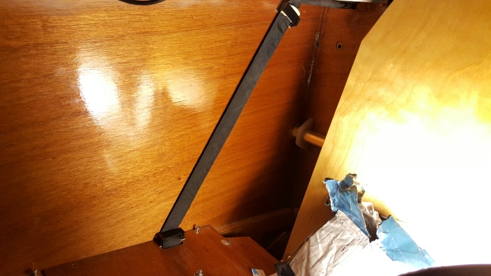
I plan to add maybe one or two more clips inside the fusealge but I need to climb in and make sure I don’t place them in a position that my elbow might hit. Right now the seat is covered with parts for electrical wiring so I’ll do that some other time. If the 3M sticky tape does not hold up I plan to secure the clips using a couple of tiny wood screws but so far the 3M tape seems adequate.
BRS Relocated
Since I am tail heavy I decided to remount the parachute moving it forward while also reducing the weight of the mounting.
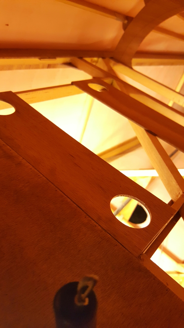
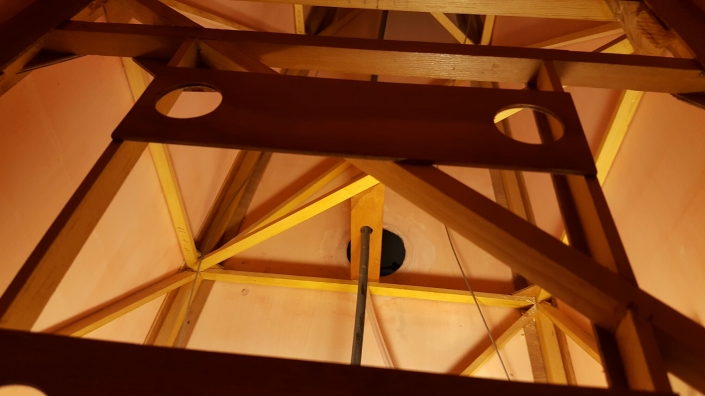
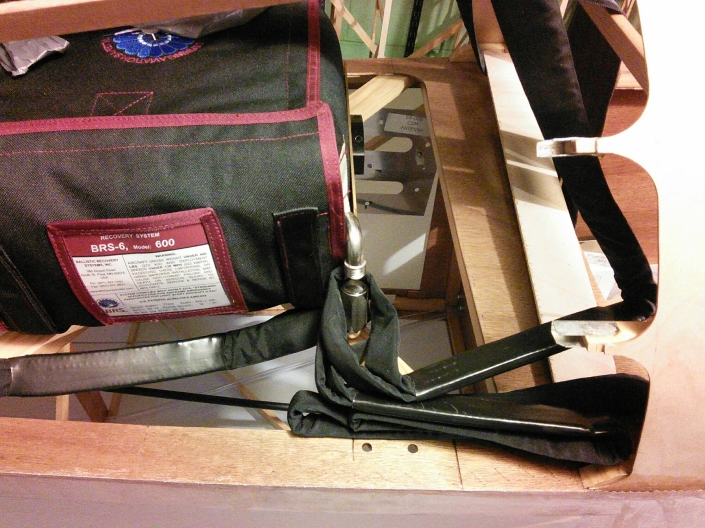
As you can see the pack can now be attached directly to the airframe and I can ditch that 1.5lbs metal bracket it came with. If your curious the manual for the BRS says this style of mounting is acceptable.
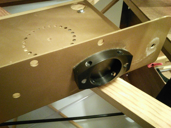
Next I made an aluminum bracket to hold the launch tube. The rocket is pointing slightly towards the rear directly between the two break away stringers and is mounted as far forward as possible.
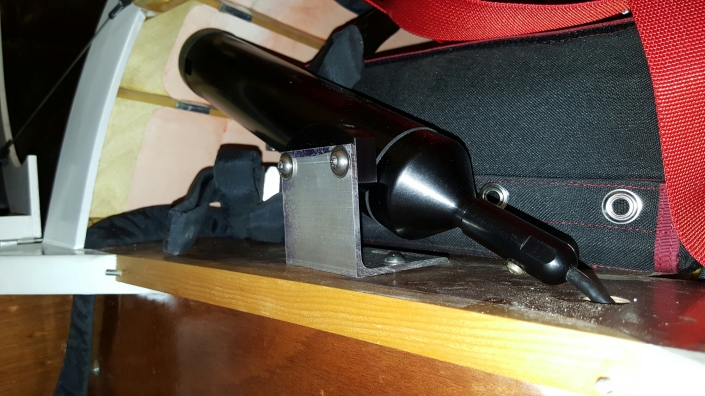
All that remains is to connect all the bridles and insert the rocket but that will be the very last step of building the airplane.
Prepare Rear Turtle Deck for Covering
Some tasks will be much easier if they are completed before covering the rear turtle deck. The first item is routing the left bridle under the center four stringers. This is necessary to ensure the left bridle is on top of the seat belts and so they can easily tear through the fabric when deployed.
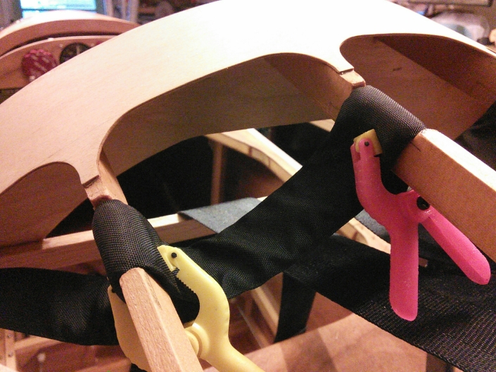
Next I used a couple drops of CA to glue some 1/16″ plywood calls over the bridle. These need to easily break away, the fabric will hold them in place, the glue is to keep them from falling off during covering.
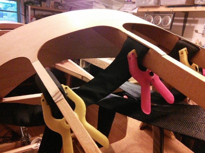
After the glue dried I sanded the caps to make smooth transitions. Next bolts were fastened to the BRS mount using some thread locker. The top of the bolts will be inaccessible later in installation so this makes it easy to tighten the mounting nuts later. The gap under the mount created by the nuts also keeps the BRS Velcro straps from being crushed.
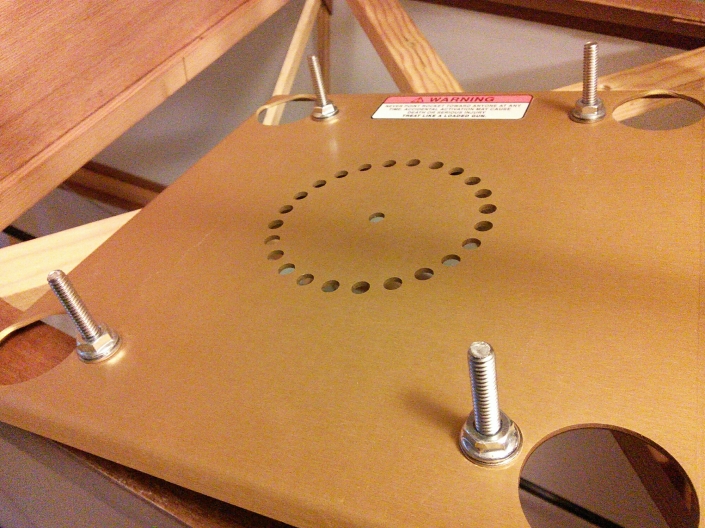
Since the rocket mount was relocated it was bolted in place using thread locker.
The BRS pack was attached to the mount with the Velcro straps.
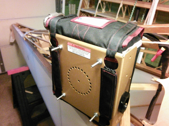
The pack can be installed through the front turtle deck opening, that will be important for future maintenance but it’s much easier to remove the break away stringers and install it through that opening. Washers were placed on top of and under the wood supports and fastened with lock nuts and thread locker.
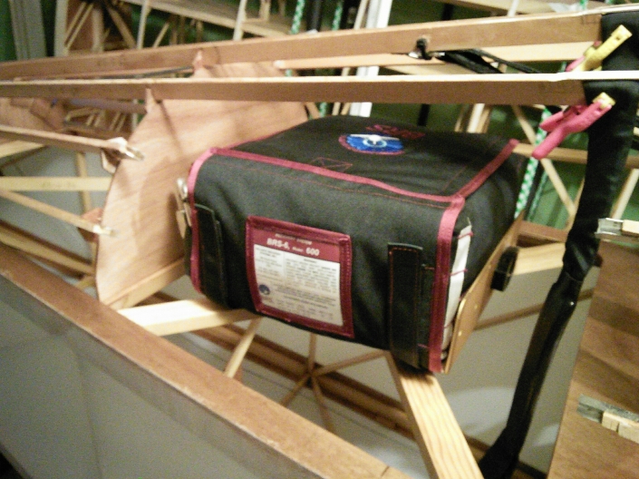
The upper bridle was bundled with some wire ties.
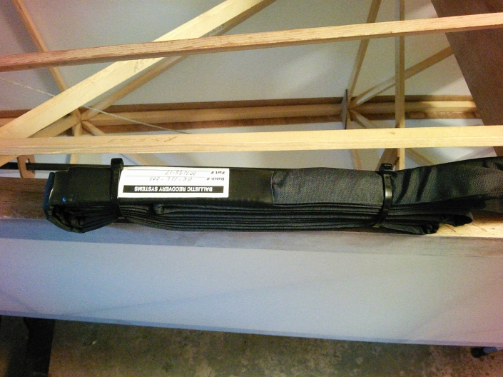
A hole was drilled into the bulkhead behind the chute and the upper bridle held in place with a wire tie.
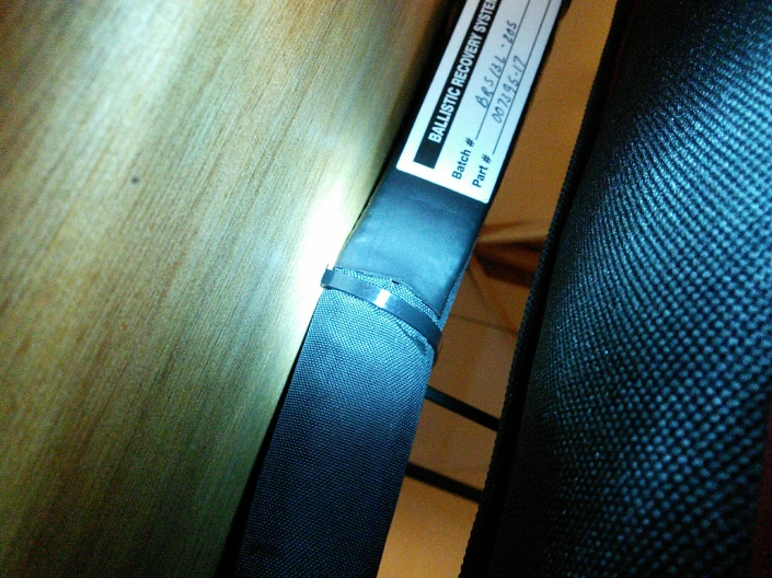
One end of the upper bridle was connected to the parachute link.
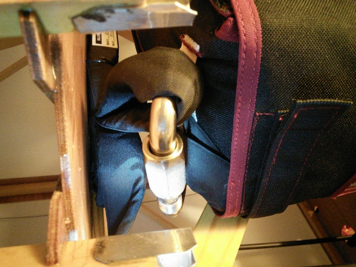
The link was closed using thread locker.
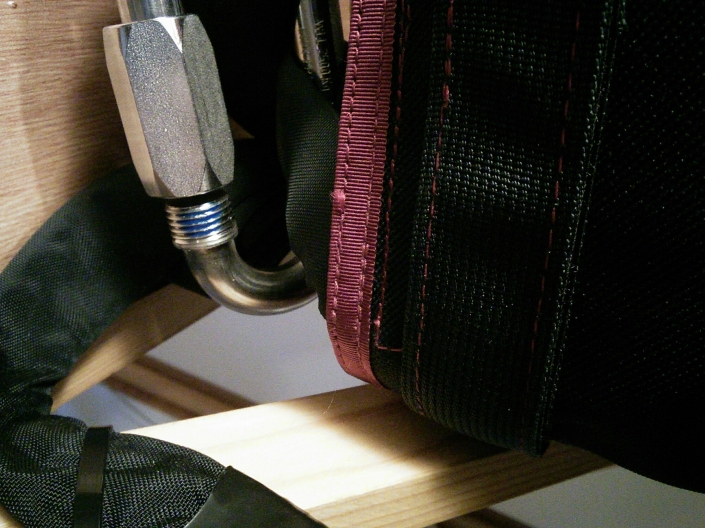
The other end of the bridle is held in place with a wire tie.
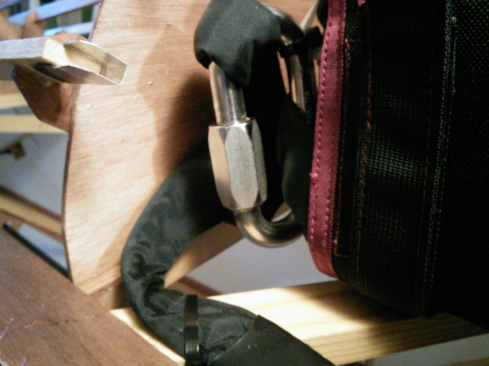
The other link was fastened to the white strip on the other side of the pack using wire ties.
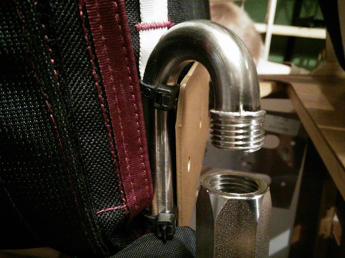
The end of the upper bridle was attached to the link.
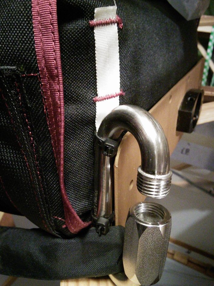
The right and left bridle will connect to the link as shown below but that step will be performed at a later date.
I did not like how the seat belt shoulder straps flop around hanging on the BRS. I added a dowel to the two center stringers and used two wire ties to support the seat belts. This is just to hold them, not for any structural purpose.
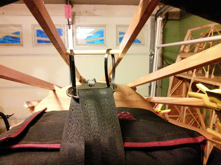
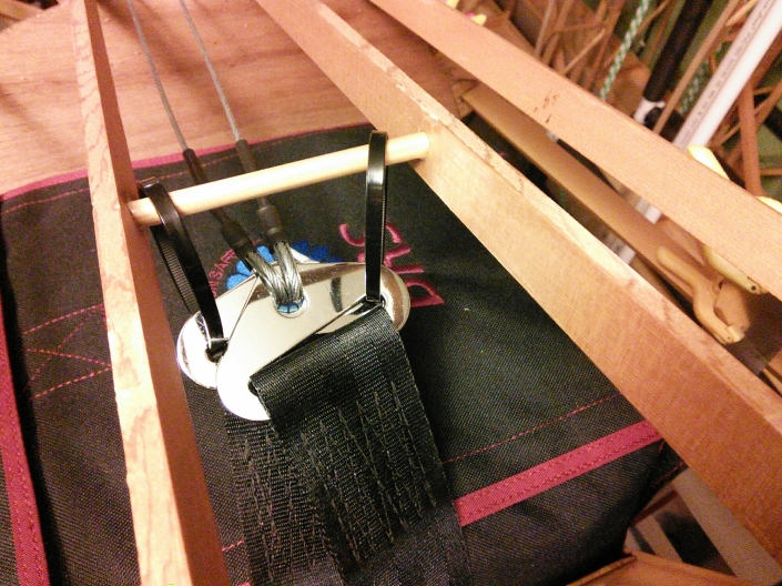
You might have noticed that the seat belts are not attached to the cables according to plans. To better understand why read the accident investigation report for G-CCAJ, you can find it here.
TLDR; attaching the shoulder straps together will help to prevent the harness from slipping off the shoulders during a crash.
In that crash the cables broke where they are mounted at the tail. To address that weakness I also modified how the cables were attached.
These safety changes deserve their own article so expect more about this in the future.
The only remaining task before covering the rear turtle deck is to mount my comm antenna. It is nice to finally see this all come together.
BRS Egress Port
The parachute needs to exit somewhere, I choose between the first and third stringer on the rear turtle deck.
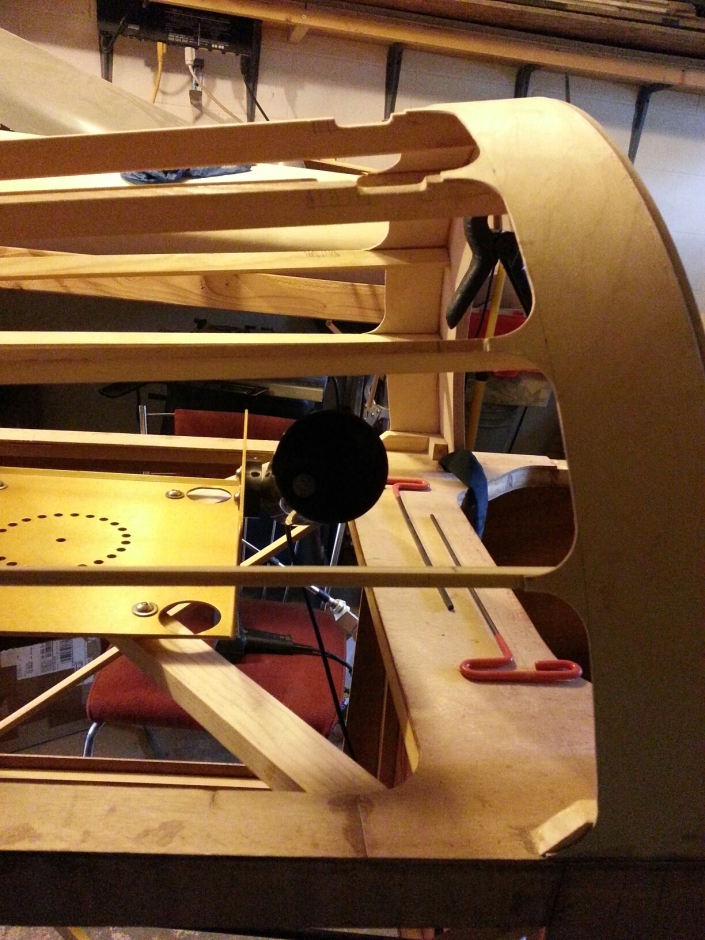
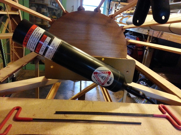
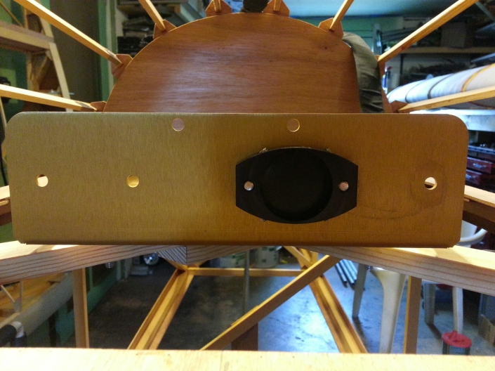
I did to move the launch tube mount toward the center, this required drilling an extra hole in the BRS mount. Be sure to use loctite on the bolts.
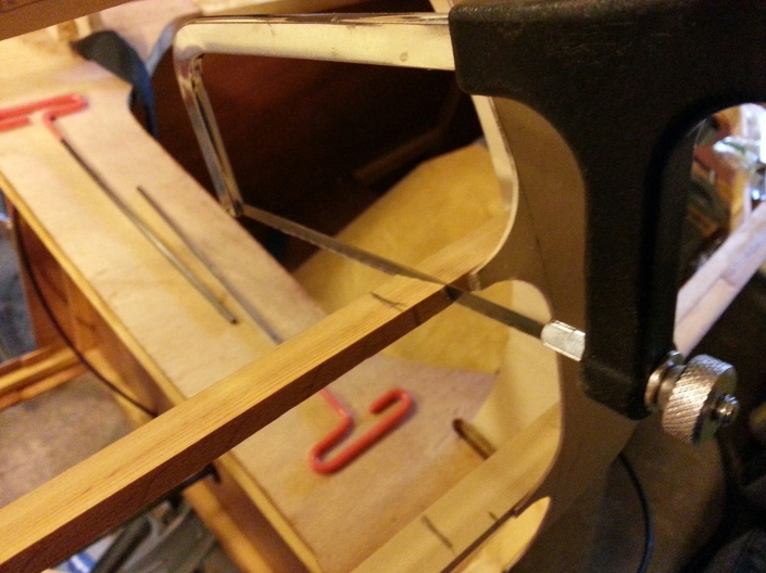
Those two at the egress port had a section cut out so they can be turned into break away stringers.
A small piece of this aluminum was cut and formed into a U shape and glued onto the bottom of each stringer. I used .016” thick aluminum. It was tough to get the nice corners needed to hold stringer at proper height.
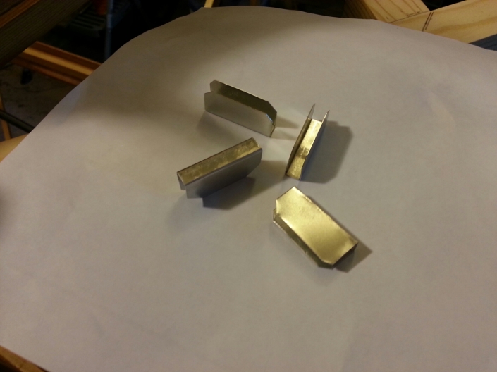
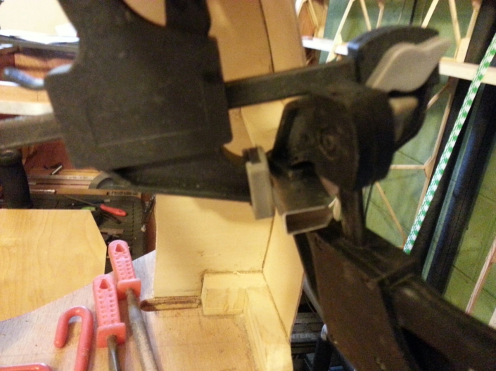
Once the glue was dry the sections that were cut off were beveled on each end.
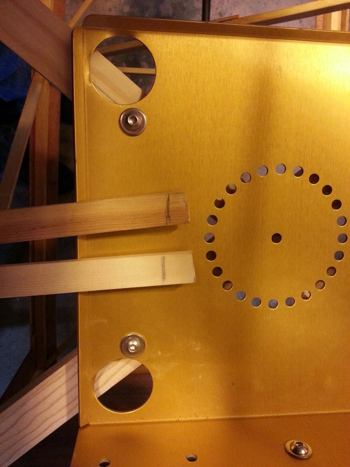
Then set into the U slots.
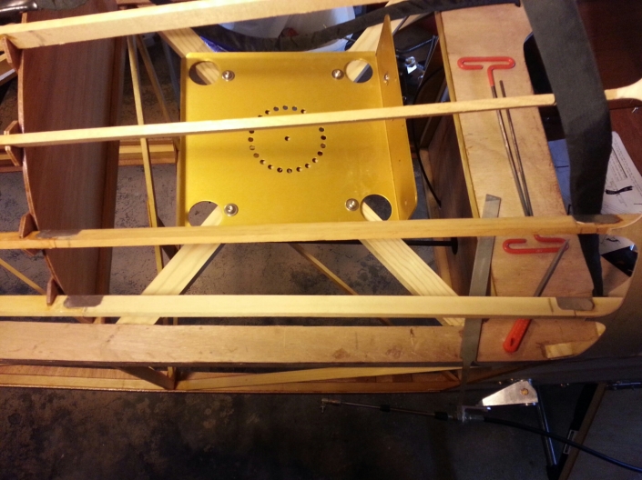
The fabric will hold these in place and the rocket will easily blow them out of the way should I ever need to deploy the parachute.
I’m sure someone will want to know why I don’t launch the rocket straight up. While that is what I wanted to do the space does not allow this.The seat belt shoulder straps go over the BRS, if the chute launched straight up it is quite likely to pull or get tangled in the shoulder straps. Risking a malfunction or my shoulders getting crushed by the seat belt did not make sense. Pulling the parachute out the side avoided conflict with the seat belt.
BRS Bridle Routing
Time to route the BRS bridles from the axle to the parachute. I first attached the bridle to the axle.
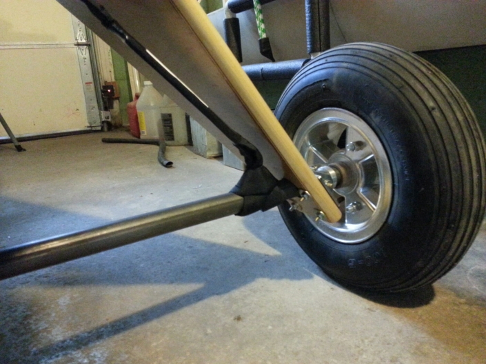
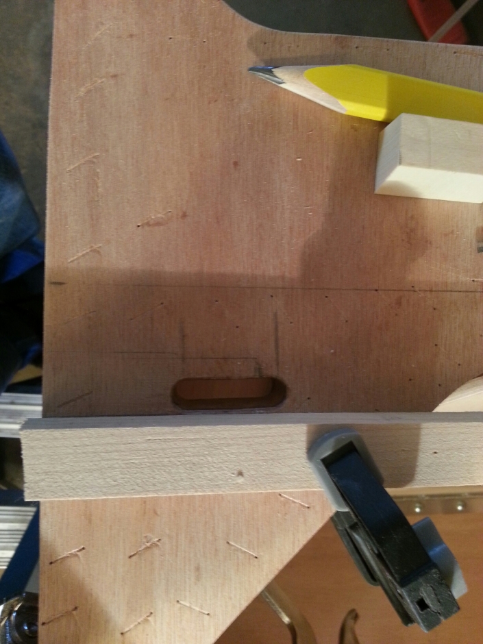
The most logical place to enter the fuselage is straight up and there already happens to be a plywood block there so I cut a short in it.
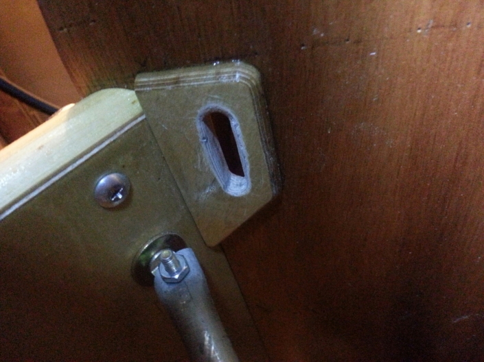
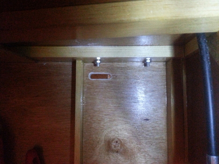
Next a slot in the seat is needed.
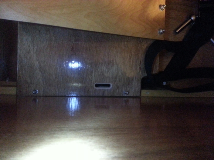
From there it’s routed through the fuselage top just in front of the rear spar carry through. Be sure that the bridle is on top of the seat belt, not under it!
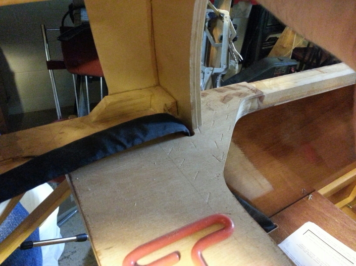
At this point the right and left routing differ. The left bridle needs to go over the shoulder harness over to the right side. Starting with the third stringer on the left, ending with the third stringer on the right a notch is cut into the top of the stringer to make room for the bridle.
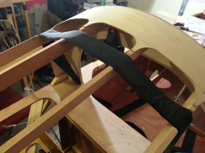
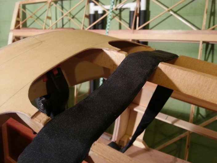
For aesthetics each slot is covered with a piece of 1/16″ plywood. This piece must easily break away so I only glued one side, the fabric will hold it in place.
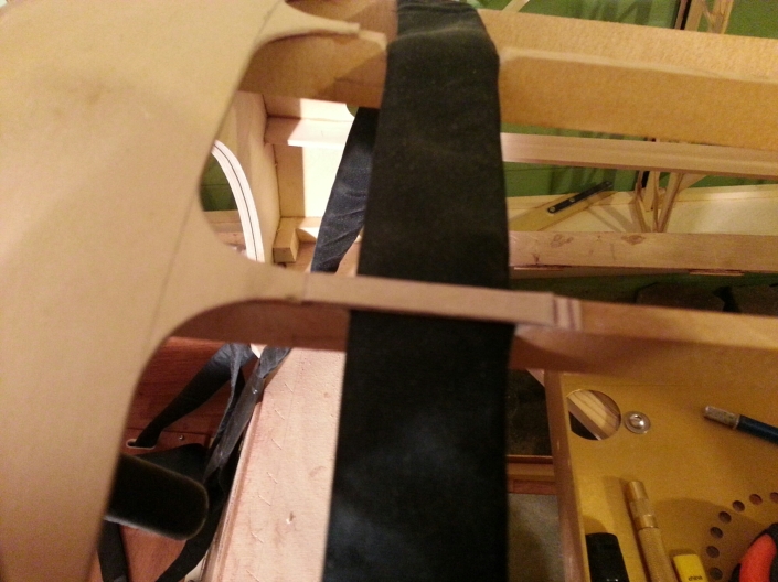
The next hassle of the BRS is the egress port. Two stringers must be modified so they can break away.
Support block for F-3A
Former 3A is mounted at an angle requiring a beveled RS-9. Since I am installing a BRS parachute I have a slight problem that also needed solved.
The left bridle for the BRS needs to be routed behind F-3A and follow the former to the other side. Trying to find an elegant way to do this while still being able to open the canopy seemed elusive. What I decided to do is move F-3A forward a couple of inches so it’s directly in front of the bridle.
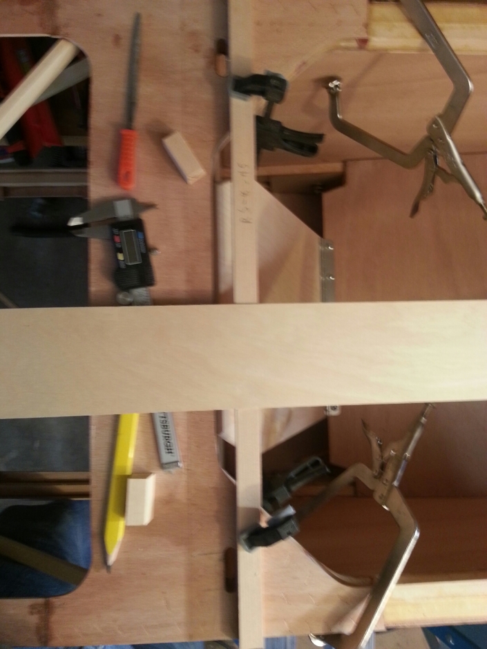
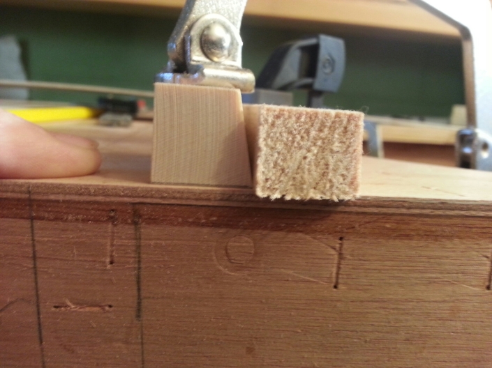
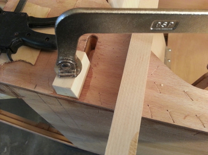
I made the RS-9 blocks that support the former and started working to mount them. I first clamped a straight edge to the fuselage where I wanted the back of F-3A located, just forward of the bridle exit points.
Then I glued the RS-9 blocks in place and clamped them. I was careful to set the block in from the edge of the fuselage to leave room for the plywood that will be glued to the block later.
Once both sides were clamped in place I removed the straight edge so it does not end up getting glued too.
Plywood Sheeting
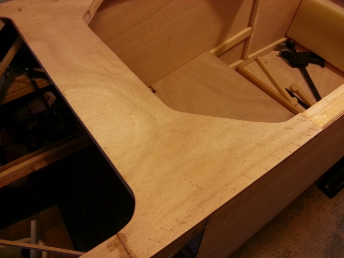
Glued the plywood sheeting to the rear cockpit area.
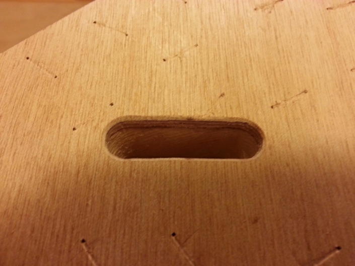
Once the glue was dry I cut out the openings for the BRS harness.
Spent the rest of the evening removing staples from the tail section.
Hope my nose wheel ships soon, being able to roll the fuselage around would be very helpful in this small garage.
Cockpit Modification for BRS
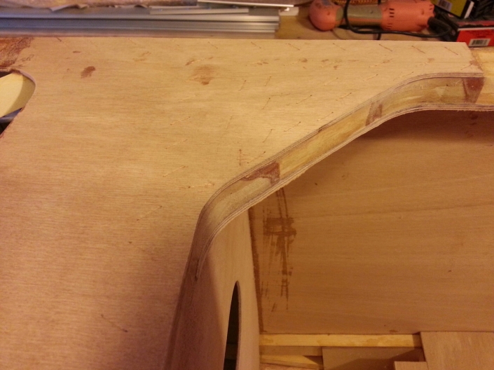
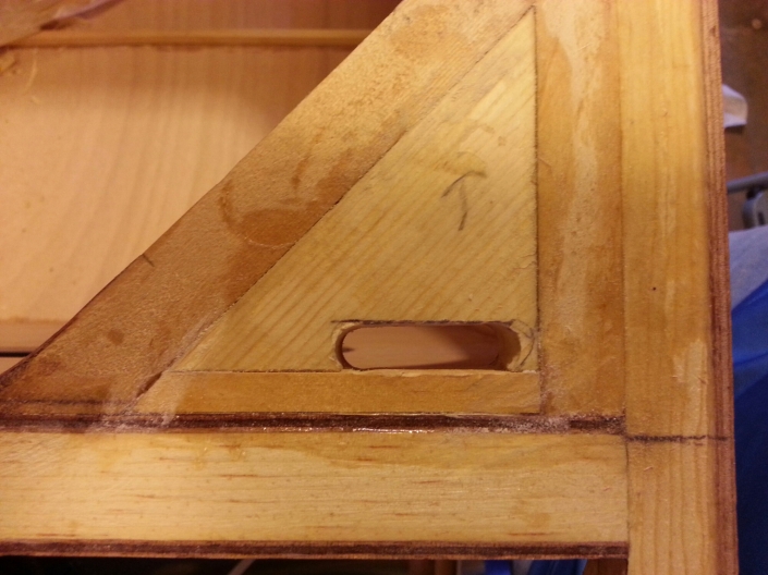
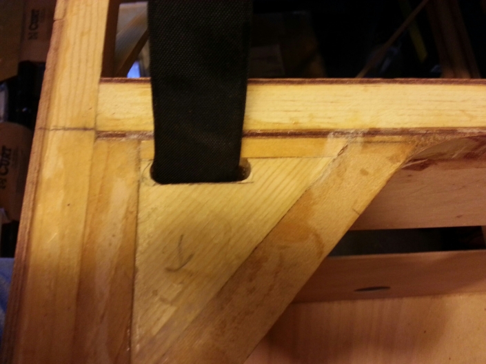
The BRS (Parachute) has two Kevlar straps that attach the fuselage to the parachute. These need to be routed through the top of the fuselage down to the landing gear. The entry point on the top is located in the rear cockpit corners. I added a wood block and cut a hole just large enough for the straps to fit through.
Once I glue the plywood sheeting on top I will radius the edges to prevent chafing of the straps.

